Hardware Wiring
This page is used as the on-site wiring checklist for the legacy Marvin Pro system. It covers dual-arm power supply, communication network, initial pose, Orin wiring, and camera deserializer wiring.
Disconnect the main power before wiring. Confirm that all Ethernet cables, power cables, and camera harnesses are firmly connected before powering on.
1. Dual-Arm Power and Communication Wiring
Complete the following wiring while the main power is disconnected:
- Connect the dual-arm robot
48V+/48V-to the positive and negative DC outputs of the220V-48Vswitching power supply. - Connect the discharge module
48V+/48V-in parallel to the same 48 V power supply. - Connect the emergency stop box in series to the robot emergency stop control loop.
- Connect the left-arm and right-arm
EthCartEthernet ports to the corresponding robot controller ports. - Connect the
12Vpower supply to the robot controller power input. - Connect the uplink Ethernet cable (Cable 1) to the robot controller network interface.
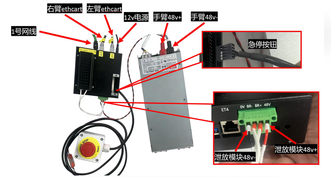
Wiring notes:
48V+and48V-polarity must be correct. Reverse connection is strictly prohibited.- Release the emergency stop button before starting the system.
- When using the system for the first time or after replacing the controller, confirm that the robot controller IP is
192.168.10.190. - During power-on, turn on the
220V-48Vswitching power supply first, then the robot controller12Vpower supply.
2. Move the Robot to the Initial Horizontal End Pose
Use fxstation or MarvinPlatform to move both arms to the initial horizontal end pose before teleoperation. The figure below uses the left arm as an example; the right arm follows the same procedure.
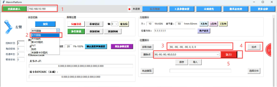
Procedure:
- Enter the robot IP address, default
192.168.10.190, and connect to the robot. - Switch the robot arm to Position Mode.
- Switch to Joint Follow mode.
- In Joint Follow mode, first return to zero position, then write the target points:
- Left arm:
[0, 0, 0, 0, 0, 0, 0]->[90, -90, -90, -90, 0, 0, 0] - Right arm:
[0, 0, 0, 0, 0, 0, 0]->[-90, -90, 90, -90, 0, 0, 0]
- Left arm:
- Click Add Point to add the current point to the trajectory list.
- Click Run. The default speed is 20%. Move the arm to the target pose.
- Exit the software after motion is complete.
Before moving the robot, confirm that there are no people, devices, or obstacles within the arm motion range.
3. Orin and Camera Deserializer Board
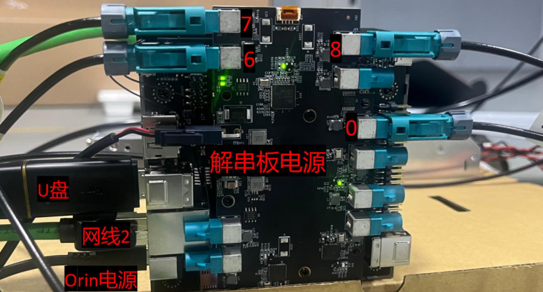
The camera deserializer board is installed at the bottom of Orin and supports up to four GMSL camera inputs. During installation, remove the Orin base first, install the deserializer standoffs and board, then reinstall the base screws.
Camera interface mapping:
| Deserializer interface number | Corresponding camera |
|---|---|
| 8 | Left-eye camera |
| 6 | Left-wrist camera |
| 7 | Right-wrist camera |
| 0 | Right-eye camera |
When connecting cameras and peripherals, connect them in order:
- Camera harnesses
- USB drive, label must be
BAG_STORAGE - Ethernet cable 2, connected to Orin
- Deserializer board power
- Orin power
4. Network Wiring
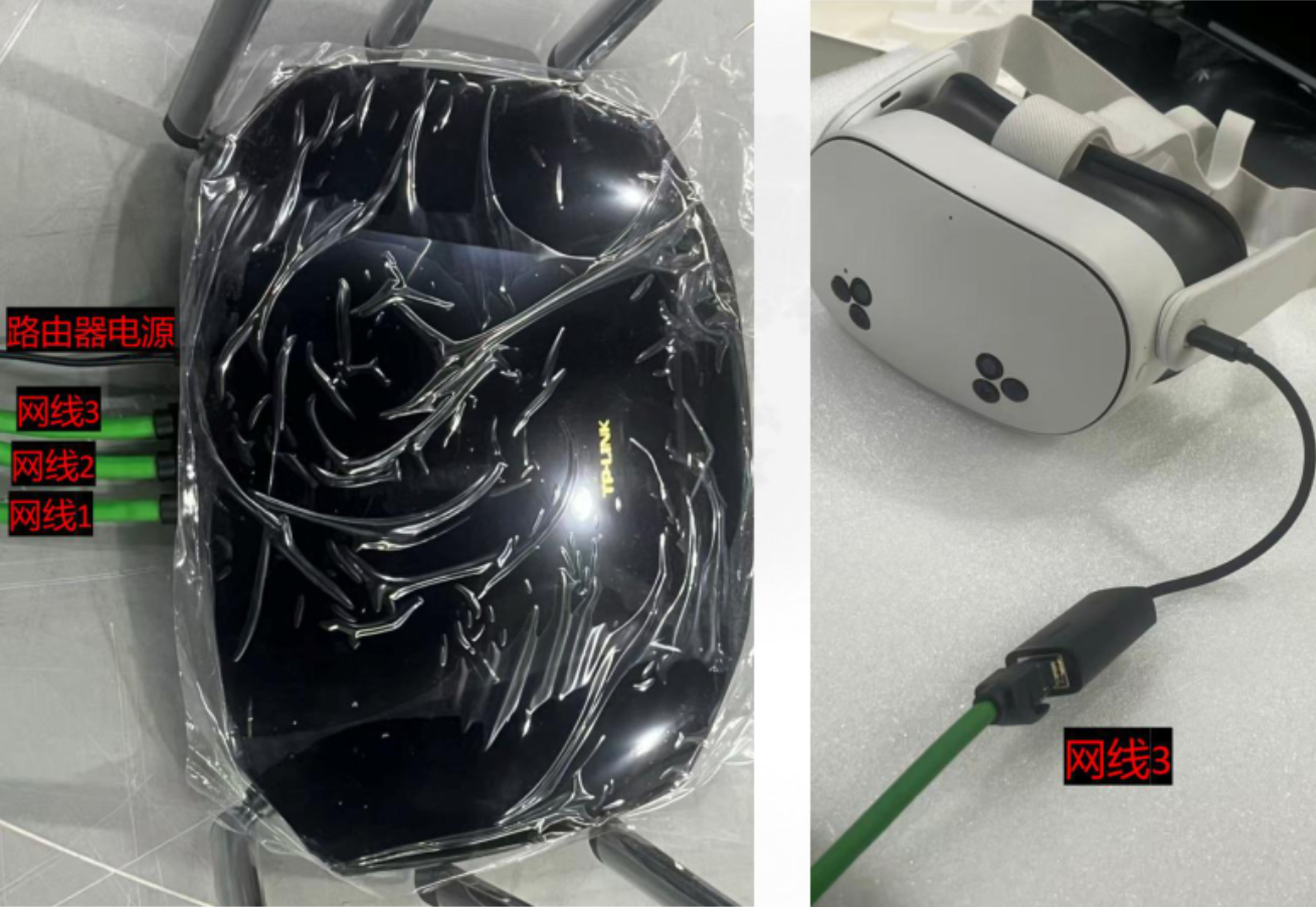
The robot controller, Orin, and VR headset adapter must be connected to the same router through Ethernet, ensuring that all three are on the same LAN.
| Cable | Connection target |
|---|---|
| Cable 1 | Connects to the robot controller |
| Cable 2 | Connects to Orin |
| Cable 3 | Connects to the VR headset adapter |
Default network parameters:
| Device | Default IP |
|---|---|
| Robot controller | 192.168.10.190 |
| Orin main controller | 192.168.10.123 |
| Router | 192.168.10.1 |
| Headset Apex app connection IP | 192.168.10.123 |
5. Power-On Check
| Step | Operation | Checkpoint |
|---|---|---|
| 1 | Turn on 48 V main power | Confirm robot-side power is normal |
| 2 | Turn on controller 12 V power | Confirm the robot controller starts normally |
| 3 | Power the deserializer board first | Wait about 10 seconds |
| 4 | Then power on Orin | Wait about 1 minute and confirm Orin startup is complete |
| 5 | Check camera interface indicators | Confirm all four camera interface indicators are steady on |
| 6 | Check network | Host PC, Orin, robot controller, and headset are on the same subnet |
If not all camera indicators are on, first check the camera harnesses, deserializer interface numbers, and deserializer power supply.